Wire harnesses are the lifelines of electrical systems, from automotive electrical networks and industrial machinery to aerospace systems and consumer electronics. Yet even the best-designed harness is only as good as its testing process. Wire harness testing is essential to verify that every connection, circuit, and component functions reliably before a system ever goes into service.
In this guide, OurPCB will explore why wire harness testing is essential for reliability and safety. We outline key testing methods and the tools used to perform them effectively. You’ll also learn step-by-step continuity testing procedures and best practices for ensuring quality and compliance.
Contents
- What is Wire Harness Testing?
- Why Testing Matters
- Types of Wire Harness Testing Methods
- 1. Visual Inspection
- 2. Continuity Testing
- 3. Short-Circuit / Open-Circuit Testing
- 4. High-Potential (HiPot) / Insulation Resistance Testing
- 5. Resistance and Milliohm Testing
- 6. Pull and Mechanical Stress Testing
- 7. Environmental Tests (Advanced)
- Tools for Wire Harness Testing
- How to Test Wire Harness for Continuity: Step-by-Step
- How to Test Wire Harness for Continuity
- Best Practices for Reliable Wire Harness Testing
- Create a Detailed Wire List / Schematic
- Use Automated Systems for Large Harnesses
- Test Before and After Assembly
- Log and Trace Results
- Conclusion | Choose OurPCB for the Right Testing Strategy
- Wire Harness Testing Methods Explained FAQs
- What standards govern wire harness testing?
- What is the difference between functional testing and electrical testing?
- Can automated testing detect intermittent faults?
What is Wire Harness Testing?
Wire harness testing refers to a set of verification procedures used to check that a wiring harness meets its design specifications and will reliably perform under real-world conditions. It is a critical step in both manufacturing and maintenance workflows because electrical faults can lead to system failure, safety hazards, or costly recalls.
Testing helps identify common issues such as miswiring or incorrect connections that can disrupt system performance. It also detects broken or open circuits, shorts between conductors, and poor crimps or loose terminals that may cause intermittent faults. Additionally, testing can reveal insulation degradation that could lead to long-term reliability or safety problems.
Effective testing ensures that each harness not only delivers power and signals correctly but also meets safety, durability, and compliance standards.
Why Testing Matters
At its core, wire harness testing ensures safety, reliability, and quality control. Whether you’re producing harnesses for automotive ECUs, industrial robots, or aerospace avionics, testing prevents field failures that could result in:
- System downtime or malfunctions
- Expensive warranty repairs
- Safety incidents due to electrical shorts or misfires
- Damage to connected equipment
In high-volume manufacturing environments, tests are also automated to streamline validation, reduce labor, and maintain consistency across every harness produced.
Types of Wire Harness Testing Methods
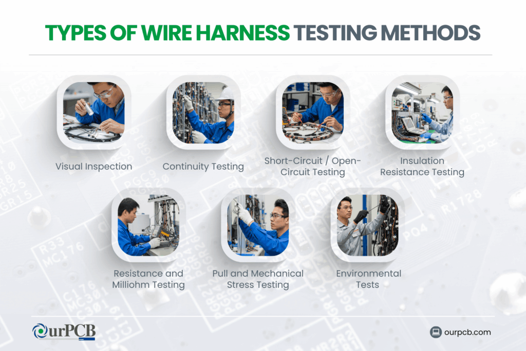
Wire harness testing covers a wide range of methods that evaluate mechanical properties, electrical integrity, and environmental resilience. Below are the key categories and techniques:
1. Visual Inspection
What it checks:
- Proper wire colors and labeling
- Correct lengths and routing
- Secure terminals and connectors
- Damage, nicks, or contamination
Before electrical tests begin, a trained inspector verifies that the harness matches the drawing and has no visible defects.
2. Continuity Testing
What it checks:
- That electrical connections are complete and unbroken
- No open circuits in any conductor
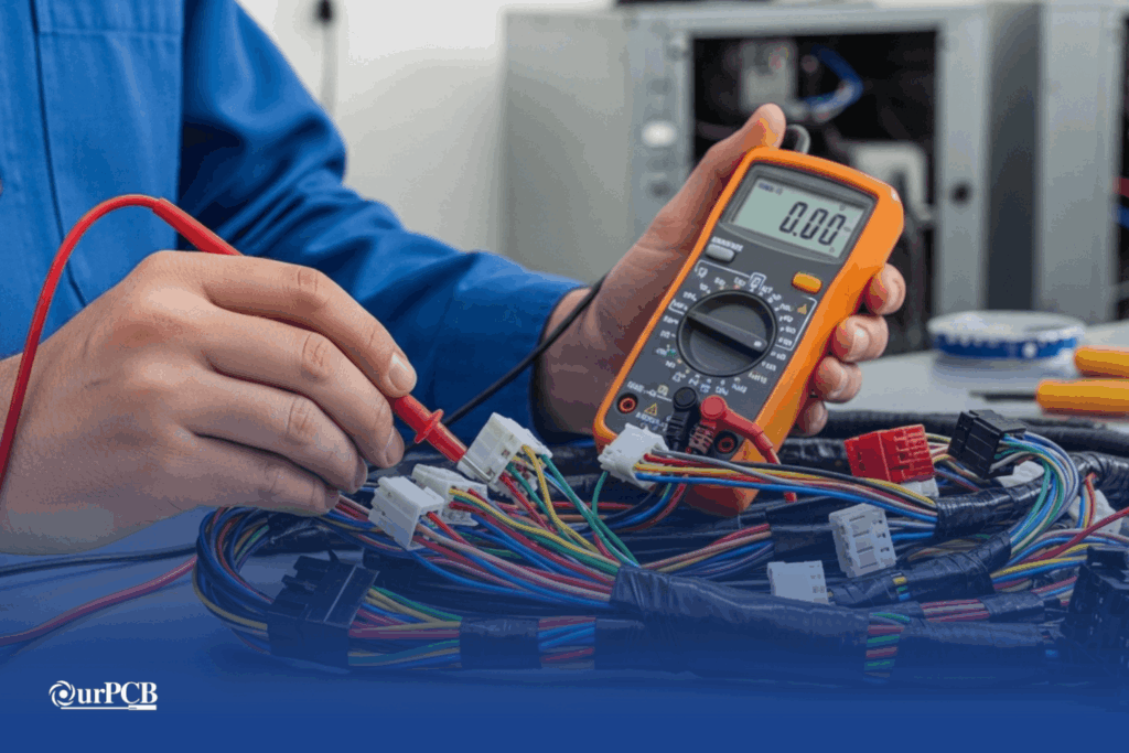
Continuity testing is often the first electrical test performed. It verifies that electricity can flow from one end of a conductor to the other without interruption. A good circuit will show a connection; broken or open circuits will not.
This method is one of the most fundamental wire harness testing techniques and is critical for catching miswires, breaks, or incorrect connections early in the process.
3. Short-Circuit / Open-Circuit Testing
After continuity checks confirm that each wire is properly connected end-to-end, short-circuit and open-circuit testing verifies that circuits are properly isolated. Short-circuit testing ensures that no unintended electrical paths exist between adjacent conductors, which could cause malfunction, overheating, blown fuses, or component damage. Open-circuit testing, on the other hand, confirms that every required connection is complete and that no breaks, incomplete crimps, or damaged wires interrupt the intended signal or power flow.
4. High-Potential (HiPot) / Insulation Resistance Testing
High-Potential (HiPot) or insulation resistance testing evaluates the integrity of a wiring harness’s insulation by applying a voltage significantly higher than its normal operating level. This elevated voltage is introduced between conductors, or between conductors and ground, to confirm that insulation materials can withstand electrical stress without leakage or breakdown. The goal is to verify that no unintended current flows through insulation that should act as a barrier.
5. Resistance and Milliohm Testing
Resistance and milliohm testing measure very low levels of electrical resistance within conductors and terminations to verify overall connection quality. Because wiring harnesses are designed to carry current efficiently, even small increases in resistance can indicate problems such as weak crimps, partially broken strands, oxidation, or improperly seated terminals.
Milliohm testing is especially important in high-current circuits, such as automotive power distribution or battery connections, where excess resistance can generate heat, reduce efficiency, and accelerate component failure.
6. Pull and Mechanical Stress Testing
Pull and mechanical stress testing evaluates the physical strength of crimped terminals and connector terminations. During this test, a controlled tensile force is applied to the wire and terminal to ensure the crimp can withstand specified pull-out forces without loosening or separating. This confirms that the mechanical bond between conductor and terminal is secure and meets industry standards.
A properly crimped and tested termination should maintain both mechanical retention and electrical integrity throughout the product’s service life.
7. Environmental Tests (Advanced)
Environmental testing validates a wiring harness’s ability to perform reliably under real-world operating conditions. In advanced applications such as automotive, aerospace, marine, and industrial systems, harnesses are exposed to simulated temperature extremes, vibration cycles, humidity, chemical exposure, and dust or water ingress to assess long-term durability. These tests replicate years of operational stress within controlled laboratory environments.
Special Offer: Get $100 off your order!
Email [email protected] to get started!
Tools for Wire Harness Testing
| Tool | Primary Function | Key Benefit |
|---|---|---|
| Test Tables | Custom fixtures that hold harnesses in place and provide standardized test points | Improves consistency and accuracy during testing |
| Multimeters | Measure continuity, resistance, and voltage | Versatile tool for general electrical diagnostics |
| Continuity Testers | Detect complete electrical paths (beep or light indicator) | Quick and simple verification of circuit integrity |
| Automated Testing Systems | Perform continuity, isolation, insulation, and other tests in high-volume environments | Fast, repeatable, reduces human error; can import wire lists and automate sequences |
How to Test Wire Harness for Continuity: Step-by-Step
Continuity testing is one of the most common and essential tests when inspecting a harness’s electrical integrity. This test verifies that current can travel uninterrupted along each wire. Here’s how:
How to Test Wire Harness for Continuity
Gather Tools
- Digital multimeter (with continuity mode)
- Alligator clips or test probes
- Harness schematic or wire list
Step 1: Safety First
Disconnect any power sources and remove the harness from powered equipment before testing — voltage on the circuit can damage the tester.
Step 2: Prepare the Multimeter
Set your multimeter to continuity mode (often indicated by a speaker icon). The device will beep when current flows.
Step 3: Test the Meter
Touch the probes together — the meter should beep or show low resistance. If it doesn’t, check batteries or probe contact quality.
Step 4: Probe Each Wire
Place one probe on one end of the wire and the second probe on the corresponding end of the same wire.
- Beep / low resistance reading: good continuity
- No beep / infinite resistance: open circuit or break
Record failed wires and follow up with visual inspection or repair if needed.
Best Practices for Reliable Wire Harness Testing
Effective wire harness testing goes beyond simply checking continuity; it requires structured procedures, documentation, and repeatable quality controls. Whether testing a small prototype assembly or a high-volume automotive harness, consistent processes ensure defects are detected early, compliance standards are met, and long-term reliability is achieved. Implementing best practices reduces rework costs, improves traceability, and strengthens overall product quality across the production lifecycle.
Create a Detailed Wire List / Schematic
A comprehensive wire list or schematic ensures every conductor, splice, and termination point is accounted for during automated or manual testing. Clear documentation minimizes the risk of missed circuits and supports accurate troubleshooting.
Use Automated Systems for Large Harnesses
As harness complexity increases, manual testing becomes time-consuming and prone to human error. Automated testing systems significantly improve speed, consistency, and measurement accuracy, especially for multi-circuit automotive or industrial harnesses.
Test Before and After Assembly
Performing interim tests during harness assembly helps identify wiring errors before crimping, soldering, or overmolding is finalized. Final validation testing confirms that the completed harness meets all electrical and mechanical requirements.
Log and Trace Results
Recording and storing test data supports quality audits, regulatory compliance, and customer requirements. Traceability also enables root-cause analysis if issues arise later in the field.
Conclusion | Choose OurPCB for the Right Testing Strategy
Wire harness testing isn’t one-size-fits-all. Your testing strategy should match the complexity of the harness and its application. OurPCB offers quality control and wire harness testing for your cable assemblies and wire harnesses.
A well-tested harness means reduced field failures, improved safety, and a smoother path from design to deployment.
Wire Harness Testing Methods Explained FAQs
What standards govern wire harness testing?
Wire harness testing is often guided by industry standards such as IPC/WHMA-A-620 for cable and wire harness assemblies, ISO standards for automotive systems, and UL requirements for safety and insulation performance. Aerospace and defense applications may also follow MIL-SPEC standards. Compliance ensures consistency, safety, and regulatory approval.
What is the difference between functional testing and electrical testing?
Electrical testing verifies continuity, resistance, isolation, and insulation integrity. Functional testing goes a step further by validating that the harness operates correctly within a real or simulated system environment, ensuring sensors, actuators, and communication lines perform as intended.
Can automated testing detect intermittent faults?
Advanced automated testers can detect intermittent faults by performing repeated cycles, vibration simulation, or dynamic flex testing. However, some intermittent issues may only appear under real-world mechanical stress or temperature changes, requiring environmental validation.
Back to Top: Wire Harness Testing Methods Explained
Special Offer: Get $100 off your order!
Email [email protected] to get started!